Error Correcting Codes
Error Correcting Codes
The techniques that we have discussed so far can detect errors, but do not correct them. Error Correction can be handled in two ways.
» One is when an error is discovered; the receiver can have the sender retransmit the entire data unit. This is known as backward error correction.
» In the other, receiver can use an error-correcting code, which automatically corrects certain errors. This is known as forward error correction.
In theory it is possible to correct any number of errors atomically. Error-correcting codes are more sophisticated than error detecting codes and require more redundant bits. The number of bits required to correct multiple-bit or burst error is so high that in most of the cases it is inefficient to do so. For this reason, most error correction is limited to one, two or at the most three-bit errors.
Single-bit error correction
Concept of error-correction can be easily understood by examining the simplest case of single-bit errors. As we have already seen that a single-bit error can be detected by addition of a parity bit (VRC) with the data, which needed to be send. A single additional bit can detect error, but it’s not sufficient enough to correct that error too. For correcting an error one has to know the exact position of error, i.e. exactly which bit is in error (to locate the invalid bits). For example, to correct a single-bit error in an ASCII character, the error correction must determine which one of the seven bits is in error. To this, we have to add some additional redundant bits.
To calculate the numbers of redundant bits (r) required to correct d data bits, let us find out the relationship between the two. So we have (d+r) as the total number of bits, which are to be transmitted; then r must be able to indicate at least d+r+1 different values. Of these, one value means no error, and remaining d+r values indicate error location of error in each of d+r locations. So, d+r+1 states must be distinguishable by r bits, and r bits can indicates 2r states. Hence, 2r must be greater than d+r+1.
2r >= d + r + 1
The value of r must be determined by putting in the value of d in the relation. For example, if d is 7, then the smallest value of r that satisfies the above relation is 4. So the total bits, which are to be transmitted is 11 bits ( d + r = 7 + 4 = 11).
Now let us examine how we can manipulate these bits to discover which bit is in error. A technique developed by R.W.Hamming provides a practical solution. The solution or coding scheme he developed is commonly known as Hamming Code. Hamming code can be applied to data units of any length and uses the relationship between the data bits and redundant bits as discussed.
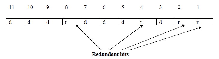
Positions of redundancy bits in hamming code
Basic approach for error detection by using Hamming code is as follows:
» To each group of m information bits k parity bits are added to form (m+k) bit code
» Location of each of the (m+k) digits is assigned a decimal value.
» The k parity bits are placed in positions 1, 2, …, 2k-1 positions.–K parity checks are performed on selected digits of each codeword.
» At the receiving end the parity bits are recalculated. The decimal value of the k parity bits provides the bit-position in error, if any.

Use of Hamming code for error correction for a 4-bit data
hamming code is used for correction for 4-bit numbers (d4d3d2d1) with the help of three redundant bits (r3r2r1). For the example data 1010, first r1 (0) is calculated considering the parity of the bit positions, 1, 3, 5 and 7. Then the parity bits r2 is calculated considering bit positions 2, 3, 6 and 7. Finally, the parity bits r4 is calculated considering bit positions 4, 5, 6 and 7 as shown. If any corruption occurs in any of the transmitted code 1010010, the bit position in error can be found out by calculating r3r2r1 at the receiving end. For example, if the received code word is 1110010, the recalculated value of r3r2r1 is 110, which indicates that bit position in error is 6, the decimal value of 110.
Example :
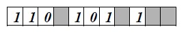
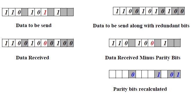
Let us consider an example for 5-bit data. Here 4 parity bits are required. Assume that during transmission bit 5 has been changed from 1 to 0 . The receiver receives the code word and recalculates the four new parity bits using the same set of bits used by the sender plus the relevant parity (r) bit for each set . Then it assembles the new parity values into a binary number in order of r positions (r8, r4, r2, r1).
Haming code Example
Calculations :
Parity recalculated (r8, r4, r2, r1) = 01012 = 510.
Hence, bit 5th is in error i.e. d5 is in error.
So, correct code-word which was transmitted is :