
Bus Topology
Bus Topology
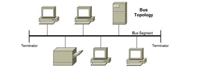
The Bus topology consists of a single cable that runs to every work-station. The bus topology is also known as linear bus. In other words, all the nodes (computers and servers) are connected to the single cable (called bus), by the help of interface connectors. This central cable is the back bone of the network and every workstation communicates with the other device through this bus.
Computers on a bus topology network communicate by addressing data to a particular computer and putting that data on the cable in the form of electronic signals. To understand how computers communicate on a bus you need to be familiar with three concepts:
i. Sending the signal
ii. Signal Bounce
iii. The Terminator
i. Sending the signal
Network data in the form of electronic signals is sent to all of the computers on the network; however, the information is accepted only by the computer whose address matches the address encoded in the original signal. Only one computer at a time can send messages.
ii. Signal Bounce
Because the data, or electronic signal, is sent to the entire network, it will travel from one end of the cable to the other. If the signal were allowed to continue uninterrupted, it would keep bouncing back and forth along the cable and prevent other computers from sending signals. Therefore, the signal must be stopped.
iii. The Terminator
To stop the signal from bouncing, a component called a terminator is placed at each end of the cable to absorb free signals. Absorbing the signal clears the cable so that other computers can send data. Every cable end on the network must be plugged into something. For example, a cable end could be plugged into a computer or a connector to extend the cable length. Any open cable ends-ends not plugged into something – must be terminated to prevent signal bounce.
In bus topology nodes are connected to the bus cable by drop lines and taps. See figure 11. A drop line is a connection running between the device and the main cable. A tap is a connector that either splices into the main cable or punctures the sheathing of a cable to create a contact with the metallic core. As a signal travels along the backbone, some of its energy is transformed into heat. Therefore, it becomes weaker and weaker as it travels farther and farther. For this reason there is a limit on the number of taps a bus can support and on the distance between those taps.
Bus Topology
Advantages of Linear Bus Topology
1. It is easy to set-up and extend bus network.
2. Cable length required for this topology is the least compared to other networks.
3. Bus topology very cheap.
4. Linear Bus network is mostly used in small networks.
Disadvantages of Linear Bus Topology
1. There is a limit on central cable length and number of nodes that can be connected.
2. Dependency on central cable in this topology has its disadvantages. If the main cable (i.e. bus) encounters some problem, whole network breaks down.
3. Proper termination is required to dump signals. Use of terminators is must.
4. It is difficult to detect and troubleshoot fault at individual station.
5. Maintenance costs can get higher with time.
6. Efficiency of Bus network reduces, as the number of devices connected to it increases.
7. It is not suitable for networks with heavy traffic.
8. Security is very low because all the computers receive the sent signal from the source.