
Cyclic Redundancy Checks (CRC)
Cyclic Redundancy Checks (CRC)
This Cyclic Redundancy Check is the most powerful and easy to implement technique. Unlike checksum scheme, which is based on addition, CRC is based on binary division. In CRC, a sequence of redundant bits, called cyclic redundancy check bits, are appended to the end of data unit so that the resulting data unit becomes exactly divisible by a second, predetermined binary number. At the destination, the incoming data unit is divided by the same number. If at this step there is no remainder, the data unit is assumed to be correct and is therefore accepted. A remainder indicates that the data unit has been damaged in transit and therefore must be rejected. The generalized technique can be explained as follows.
If a k bit message is to be transmitted, the transmitter generates an r-bit sequence, known as Frame Check Sequence (FCS) so that the (k+r) bits are actually being transmitted. Now this r-bit FCS is generated by dividing the original number, appended by r zeros, by a predetermined number. This number, which is (r+1) bit in length, can also be considered as the coefficients of a polynomial, called Generator Polynomial. The remainder of this division process generates the r-bit FCS. On receiving the packet, the receiver divides the (k+r) bit frame by the same predetermined number and if it produces no remainder, it can be assumed that no error has occurred during the transmission. Operations at both the sender and receiver end
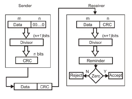
Basic scheme for Cyclic Redundancy Checking
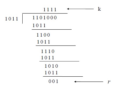
This mathematical operation performed is illustrated in Fig. by dividing a sample 4-bit number by the coefficient of the generator polynomial x3+x+1, which is 1011, using the modulo-2 arithmetic. Modulo-2 arithmetic is a binary addition process without any carry over, which is just the Exclusive-OR operation. Consider the case where k=1101. Hence we have to divide 1101000 (i.e. k appended by 3 zeros) by 1011, which produces the remainder r=001, so that the bit frame (k+r) = 1101001 is actually being transmitted through the communication channel. At the receiving end, if the received number, i.e., 1101001 is divided by the same generator polynomial 1011 to get the remainder as 000, it can be assumed that the data is free of errors.
Cyclic Redundancy Checks
The transmitter can generate the CRC by using a feedback shift register circuit. The same circuit can also be used at the receiving end to check whether any error has occurred. All the values can be expressed as polynomials of a dummy variable X. For example, for P = 11001 the corresponding polynomial is X4+X3+1. A polynomial is selected to have at least the following properties:
o It should not be divisible by X.
o It should not be divisible by (X+1)
The first condition guarantees that all burst errors of a length equal to the degree of polynomial are detected. The second condition guarantees that all burst errors affecting an odd number of bits are detected.
CRC is a very effective error detection technique. If the divisor is chosen according to the previously mentioned rules, its performance can be summarized as follows:
→ CRC can detect all single-bit errors
→ CRC can detect all double-bit errors (three 1’s)
→ CRC can detect any odd number of errors (X+1)
→ CRC can detect all burst errors of less than the degree of the polynomial.
→ CRC detects most of the larger burst errors with a high probability.
→ For example CRC-12 detects 99.97% of errors with a length 12 or more